





loading
| Availability: | |
|---|---|


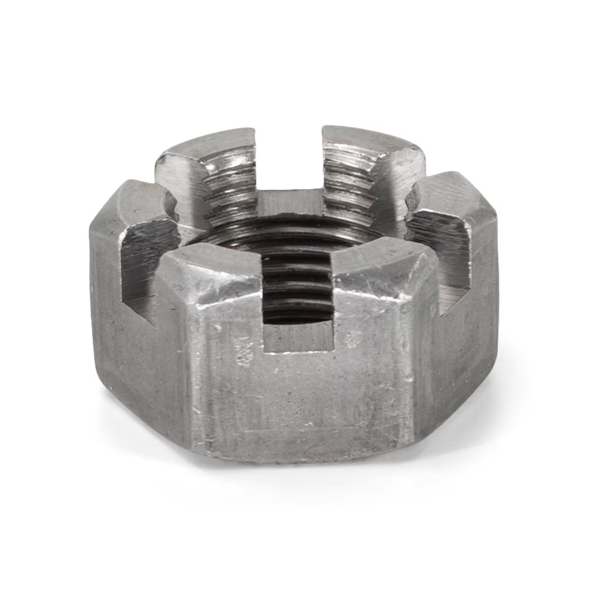
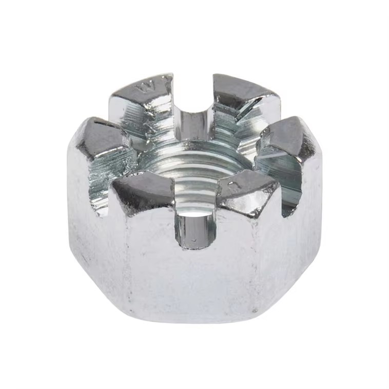
The locking function depends on three matched components:
a DIN 935 slotted nut;
a bolt, stud or shaft with a correctly positioned cross-hole;
a suitable cotter pin.
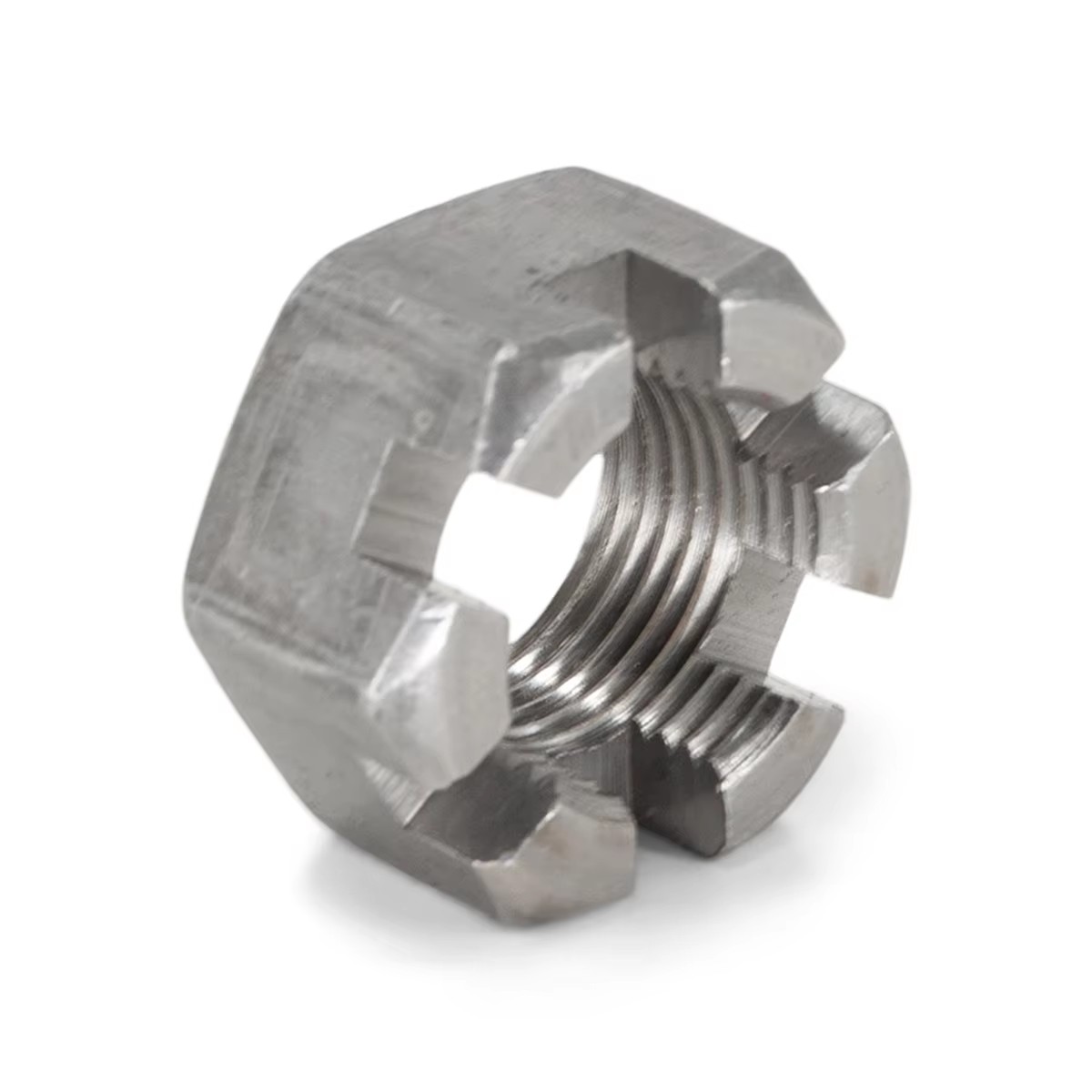
The nut is tightened to the specified installation condition. One pair of slots is then aligned with the cross-hole, and the cotter pin is inserted and secured. The completed assembly provides a direct visual indication that the nut has been mechanically retained.
The slots alone do not lock the joint. The cotter pin and the drilled mating component are essential parts of the locking system.
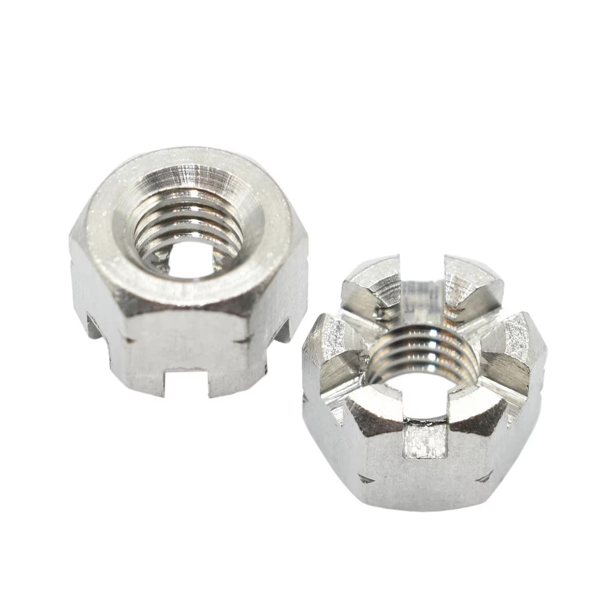
The six-sided body allows the nut to be installed with standard tightening tools. The wrench size, installation torque and final preload must be selected according to the thread, material, mating components and engineering specification.
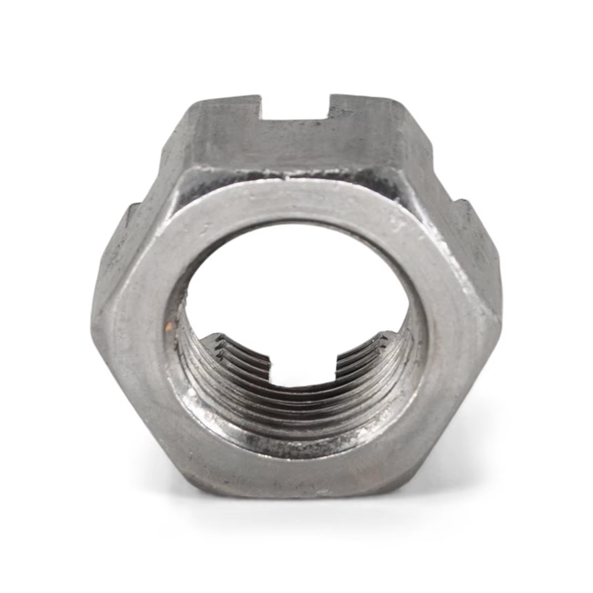
The upper slots provide multiple alignment positions for the cotter pin. Final adjustment should follow the assembly drawing or installation procedure rather than an assumed torque value.
The internal thread must match the mating bolt or shaft in diameter, pitch and tolerance. Cross-threading, damaged threads or an incorrect fit can compromise both installation and retention.
Specification | Description |
|---|---|
Product type | Hexagon Slotted Nut |
Standard | DIN 935 |
Locking method | Cotter pin through the nut slot and mating cross-hole |
Material | Carbon steel is listed for the referenced WF Fastener product; confirm for each order |
Surface treatment | Zinc plating is listed for the referenced product; confirm color and coating specification |
Thread system | Confirm diameter, pitch and tolerance in the RFQ |
Property class | Confirm before production |
Dimensions | Confirm against the applicable DIN 935 requirement and purchase drawing |
Cotter pin | Normally specified separately; confirm size and supply scope |
provides positive mechanical retention after pin installation;
allows straightforward visual inspection of the locking condition;
helps prevent unintended nut rotation in vibration-sensitive assemblies;
supports maintenance procedures that require a defined retained position;
can be removed during servicing by replacing the cotter pin;
uses a familiar hexagonal tool interface for installation.
DIN 935 slotted nuts may be used in:
wheel hubs and axle assemblies;
steering and suspension linkages;
agricultural machinery;
construction equipment;
rotating shaft assemblies;
bearing retention points;
clevis and pivot connections;
industrial machinery settings that must remain mechanically secured.
The nut, bolt or shaft, cotter pin and joint design must be evaluated as a complete system. Suitability for a safety-critical application should be confirmed by the responsible engineer.
Confirm the thread diameter, pitch and fit before assembly.
Inspect the nut, mating thread and cross-hole for damage or contamination.
Tighten the nut according to the approved assembly procedure.
Align the nearest suitable slot with the cross-hole without exceeding the permitted installation condition.
Insert the specified cotter pin fully through the aligned opening.
Secure the pin according to the applicable installation instruction.
Verify that the pin is seated correctly and that the nut cannot rotate past the retained position.
Replace a used or deformed cotter pin during reassembly unless the engineering procedure states otherwise.
Do not assume that every product described as a “castle nut” is dimensionally identical to DIN 935.
A slotted nut should not be confused with a prevailing-torque nut or nylon insert lock nut.
The locking effect is mechanical and depends on correct pin installation.
Material grade, coating thickness, corrosion resistance and test requirements must be stated in the order.
A flange is not treated as a standard DIN 935 feature in this description; any flanged variant must be confirmed separately by drawing.
A slotted nut has openings in its upper section for a cotter pin. A standard hex nut does not provide this pin-locking interface.
The primary clamping function is provided by the threaded joint. The cotter pin is used to restrict unintended nut rotation and should not be treated as a substitute for correct joint design.
Reuse depends on the condition of the threads, slots, coating and mating components. The cotter pin should be inspected and normally replaced after removal.
The standard designation does not remove the need to specify the required material, property class, coating and inspection criteria in the purchase order.
Please provide the thread size and pitch, material, property class, surface treatment, quantity, mating bolt or shaft details, cotter-pin requirement and application conditions.
Submit the requirement through the WF Fastener contact page or review the current Slotted Nut category.