
 English


Views: 0 Author: Site Editor Publish Time: 2026-08-17 Origin: Site


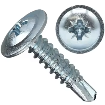
Fastener failure in metal construction rarely comes down to a bad batch of steel. You usually have a specification error on your hands. When you mismatch drill point capacity and metal thickness, you get drill point burnout, stripped threads, and joint jacking. Procurement and engineering teams often confuse screw diameter with drilling capacity. That mistake leads to costly rework and compromised structural integrity on the job site.
Unlike standard fasteners, self-drilling screws handle a multi-step process. They drill a pilot hole and tap their own thread channels to lock the joint together in one motion. If the geometry is wrong, the connection fails. If the drill point is too short, the threads engage early and snap the shank. If the thread pitch is wrong, the connection strips out under wind uplift loads.
This guide breaks down how to select the right fasteners. We will match drill points to Total Material Thickness (TMT) and show you how to stop common installation failures before they happen.
Drill Point Dictates Capacity: The Tek point size (e.g., #2 through #5), not the screw diameter, determines the maximum metal thickness the fastener can penetrate without burning out.
Total Material Thickness (TMT) is Critical: Accurate specification requires calculating the combined thickness of all materials being joined, plus any gaps, to ensure the unthreaded drill point clears the metal before threads engage.
Self-Drilling vs. Self-Tapping: True self-drilling screws feature a drill-bit tip to cut through metal, whereas self-tapping screws only cut threads and strictly require a pre-drilled pilot hole.
Thread Pitch Matches Material: Coarse threads are required for thin sheet metal to prevent stripping, while fine threads are necessary for heavy structural steel to maximize engagement.
Material and Coating Impact Performance: Selecting between carbon steel, 410 stainless, or bi-metal fasteners requires evaluating environmental exposure against the hardness of the base metal.
Table of Contents
Misinterpreting fastener nomenclature leads directly to incorrect load capacities and massive installation failures. A primary industry error involves confusing self-drilling screws with self-tapping screws. This single mistake results in snapped heads, ruined metal substrates, and delayed project timelines. True self-drilling fasteners feature a distinct fluted tip designed to cut raw metal. Understanding standard industry callouts allows you to instantly identify the gauge, threads per inch (TPI), and overall length required for the connection.
Standard designations carry specific mechanical properties. When you look at a box of fasteners, you need to know exactly what the numbers mean before driving them into steel. Navigating self drilling screw sizes means looking at the spectrum from small #6 HVAC screws to large 5/16" structural fasteners. In industrial lightweight construction, diameters typically range from 4.8 mm to 8.0 mm.
Here is how you decode a standard imperial callout like 12-14 x 1-1/4":
Gauge or Diameter: The first number (12) represents the shank diameter. A #12 screw is approximately 0.216 inches thick.
Threads Per Inch (TPI): The second number (14) indicates how many threads sit within one inch of the shank.
Overall Length: The final number (1-1/4") dictates the total length of the fastener from under the head to the very tip of the drill point.
The diameter directly dictates the shear and tensile strength of the connection. A larger diameter provides higher shear capacity, resisting the lateral forces that attempt to slide joined materials apart. However, increasing the diameter also requires more torque to drive the fastener, which can distort thin metal profiles if not managed correctly. You cannot simply upsize the diameter to fix a failing joint; you must match the diameter to the structural load requirements and the base metal thickness.
Evaluating Threads Per Inch (TPI) requires matching the thread pitch to the substrate hardness and thickness. You face a mechanical trade-off between thread spacing and pull-out resistance across varying metal gauges. Coarse threads, which have a lower TPI, grab thin sheet metal aggressively. The wider spacing captures more material between each thread, preventing the threads from tearing out the substrate under tension.
Fine threads, featuring a higher TPI, engage heavy structural steel effectively. Thick steel provides ample material for multiple threads to bite into. The tighter thread spacing maximizes the surface area contact within the tapped hole, generating massive pull-out resistance. Using a fine thread in thin sheet metal almost guarantees stripping, as the threads sit too close together and simply ream out the hole.
Recommended Thread Pitch by Substrate Thickness
Substrate Thickness | Recommended TPI | Primary Application |
|---|---|---|
26-gauge to 18-gauge | 14 to 16 TPI (Coarse) | Metal roofing, wall panels, HVAC ductwork |
16-gauge to 1/8 inch | 14 TPI (Medium) | Light gauge steel framing, track and stud |
1/8 inch to 1/4 inch | 12 to 14 TPI (Fine) | Heavy purlins, structural clips |
1/4 inch to 1/2 inch | 24 TPI (Ultra-Fine) | Thick I-beams, heavy structural steel |
Defining grip range versus overall length is another mandatory specification step. The overall length measures the fastener from under the head to the tip of the drill point. The grip range indicates the actual thickness of material the fastener can securely hold. These two measurements are never the same.
The length of the drill flute must exceed the thickness of the material being drilled. If the threads engage the metal before the drill point finishes cutting through the substrate, the fastener binds. The threads attempt to pull the screw forward faster than the point can remove metal. This forces the fastener to snap under extreme torsional load or strips the newly cut threads, destroying the connection's holding power. When fastening a 2-inch insulated metal panel to a steel purlin, you need a fastener long enough to clear the panel, clear the insulation, and drill completely through the purlin before the threads bite into the top sheet.
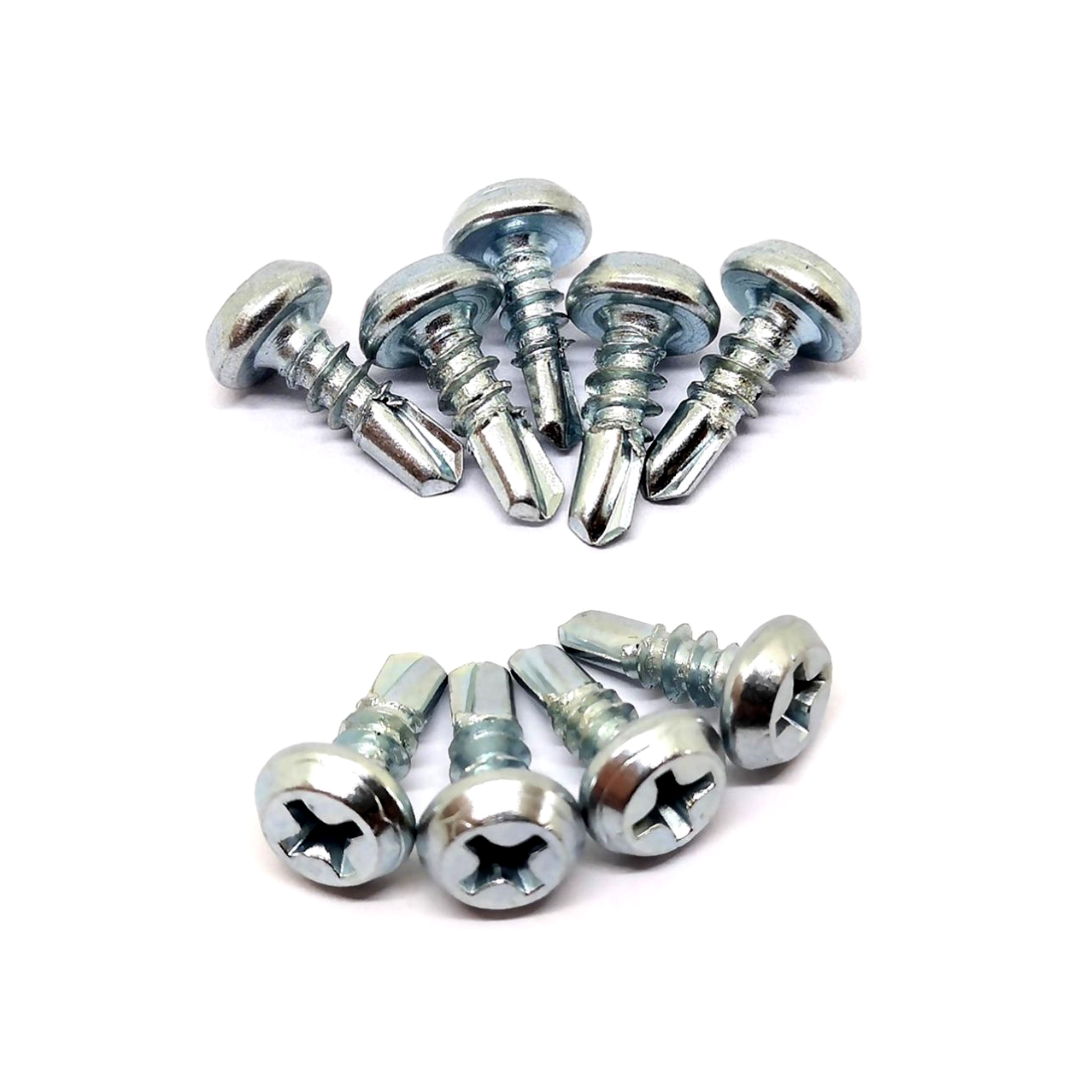
Categorizing drill points by their engineering limits prevents job site failures. The Tek numbering system standardizes these limits based on drill point length and flute design. You cannot force a small drill point through thick steel simply by applying more pressure. The geometry of the point dictates its maximum cutting capacity.
Tek 2 and Tek 3 points handle thin to medium gauge steel applications. A Tek 2 point typically penetrates up to 0.110 inches, making it optimal for 26-gauge up to 18-gauge steel. Moving to a Tek 3 extends the drilling capacity up to 0.175 inches (4.5mm).
These points feature shorter flutes designed to cut quickly through thin substrates without wandering off center. Because the metal is thin, chip evacuation happens rapidly, requiring minimal flute length to clear the debris. Installers use these fasteners daily for attaching metal lath, securing drywall to steel studs, and fastening lightweight cladding.
Tek 2 Applications: HVAC duct assembly, standing seam roof clips to light gauge decking, interior steel framing.
Tek 3 Applications: Corrugated metal panels to 14-gauge purlins, commercial gutter installation, heavy track framing.
Tek 4 and Tek 5 points are engineered specifically for heavy structural steel. A Tek 4 fastener handles steel up to 1/4 inch thick, while a Tek 5 fastener can penetrate structural steel up to 1/2 inch (12.7mm) thick.
These fasteners feature elongated flutes designed to evacuate large volumes of metal chips from deep holes. As the point cuts deeper into thick steel, the displaced metal must escape. Without these extended flutes, metal shavings pack tightly into the hole. This packing causes the drill point to overheat, lose its temper, and fail instantly. Driving a Tek 5 fastener requires steady pressure and strict adherence to RPM limits to maintain the cutting edge through half an inch of solid steel. You cannot run a Tek 5 screw at 2500 RPM; you must gear down to 1500 RPM to prevent burning the point.
Specialty points address unique fastening challenges where standard points fail. Screws with an undercut beneath the head are specifically designed for thin sheet metal connections. When a standard screw seats against thin metal, the final turn often strips the threads. The undercut absorbs the material displacement and provides a relief zone, preventing over-driving and thread stripping.
Reduced drill points allow installers to stitch thin metal panels together without tearing the substrate. The drill point is slightly smaller than the root diameter of the threads. This ensures the threads aggressively bite into the thin metal rather than sliding through an oversized pilot hole, ensuring a tight, weather-resistant seal on side laps.
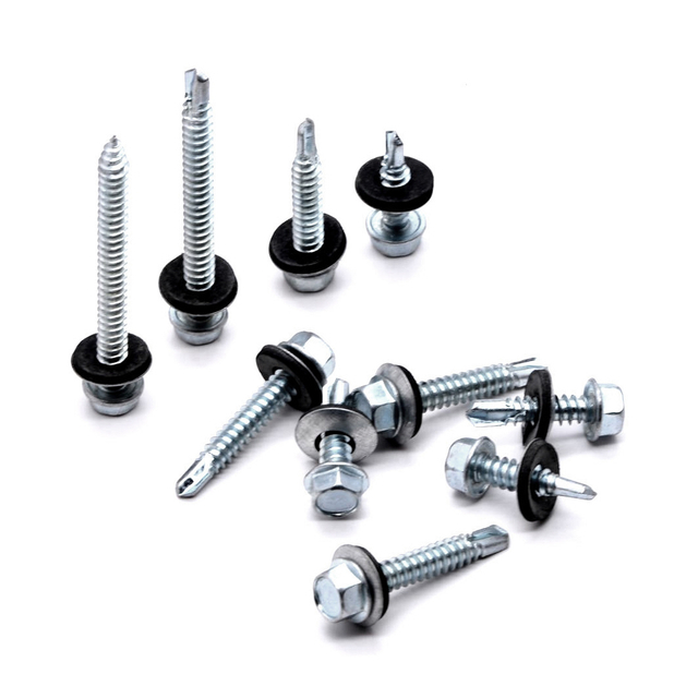
Technical specification requires a strict step-by-step framework. Guessing the required size leads directly to structural liability and failed inspections. Selecting the correct self drilling screw sizes demands evaluating the entire joint configuration before looking at load tables.
Total Material Thickness (TMT) is the absolute baseline for fastener selection. You must account for every layer the screw will penetrate. Use the formula: Thickness of Material A + Thickness of Material B + Any voids, sealants, or insulation between them.
For example, fastening a 1/8-inch steel bracket to a 1/4-inch steel tube with a 1/16-inch gap between them creates a TMT of 7/16 inches. The unthreaded drill flute must be longer than 7/16 inches. If it is shorter, the threads hit the bracket before the point clears the tube. The threads feed at a fixed rate per revolution, but the drill point cuts at a slower rate. The screw binds and snaps. Failing to calculate the exact TMT guarantees fastener failure.
Match the calculated TMT to the manufacturer's maximum drilling capacity for specific Tek points. The unthreaded portion of the drill point must be longer than the total thickness of the materials being joined.
If you ignore this step, you risk thread engagement prior to drilling completion. When threads engage the top material while the point is still cutting the bottom material, the threads pull the screw forward at a fixed rate. If the point cannot cut metal fast enough to match that rate, the screw binds and snaps under the extreme torsional load.
Standard Tek Point Drilling Capacities
Tek Point Size | Maximum Drilling Capacity (Inches) | Maximum Drilling Capacity (mm) | Typical Application |
|---|---|---|---|
Tek 2 | 0.110" | 2.8 mm | Sheet metal to light framing |
Tek 3 | 0.175" | 4.5 mm | Metal panels to medium purlins |
Tek 4 | 0.250" | 6.4 mm | Heavy cladding to structural steel |
Tek 5 | 0.500" | 12.7 mm | Direct fastening to thick I-beams |
Cross-reference manufacturer shear and tensile load tables to specify the diameter. Balance the structural requirements with the physical constraints of the fastening flange.
A massive 5/16" diameter fastener might meet the extreme shear load requirements of the design, but it could split a narrow steel flange or require excessive installation torque that operators cannot safely manage. Select a diameter that provides the necessary safety factor for wind uplift and shear forces without overpowering the base material. You must also verify that the chosen diameter does not violate edge distance requirements on the steel framing.
Ensure at least three full threads protrude past the back side of the structural substrate. This protrusion guarantees maximum pull-out strength. The tapered drill point provides zero holding power. If the fastener stops with the drill point resting inside the steel substrate, the connection will fail under tension. The fully formed threads must carry the structural load entirely. Add the TMT, the required thread protrusion, and the drill point length together to find your minimum overall fastener length.
Assessing long-term reliability dictates the value of engineered fasteners. Standard self-drilling screws are cold-headed from basic steel wire and mass-produced for general applications. Engineered fasteners undergo precise heat treatments to balance drill-point hardness with shank ductility. A hard point cuts metal efficiently; a ductile shank flexes under building movement and thermal expansion without snapping.
Carbon steel fasteners offer high hardness, making them excellent for drilling through thick structural steel. However, carbon steel rusts rapidly when exposed to moisture and requires heavy protective coatings to survive exterior environments. Manufacturers heat-treat these screws to achieve the necessary surface hardness for cutting steel.
410 Stainless Steel provides moderate corrosion resistance but lacks the extreme hardness of heat-treated carbon steel. Installers limit 410 stainless fasteners to drilling softer metals like aluminum or very thin steel. Attempting to drive a 410 stainless screw into heavy structural steel usually results in a dulled point and a failed installation.
Bi-Metal fasteners solve this material limitation through friction welding. Manufacturers weld a 300-series stainless steel body to a hardened carbon steel drill point. The carbon steel point cuts through heavy steel effortlessly. Once installed, the carbon steel point sits inside the building envelope, while the 300-series stainless head remains exposed to the elements, providing maximum immunity to environmental corrosion.
Evaluating environmental compliance involves matching the fastener coating to the specific site exposure. Zinc plating serves basic interior needs where moisture remains low. Mechanical galvanizing provides a thicker barrier for standard exterior applications.
Proprietary multi-layer coatings protect against aggressive exterior environments, including coastal zones and chemical plants. Match the coating to environmental corrosivity categories defined by standards like ISO 12944. Specifying a C5-rated coating ensures the fastener will not degrade prematurely when exposed to high salinity or industrial pollutants. Using an interior-rated zinc screw on an exterior metal roof guarantees rapid galvanic corrosion and structural failure within years.
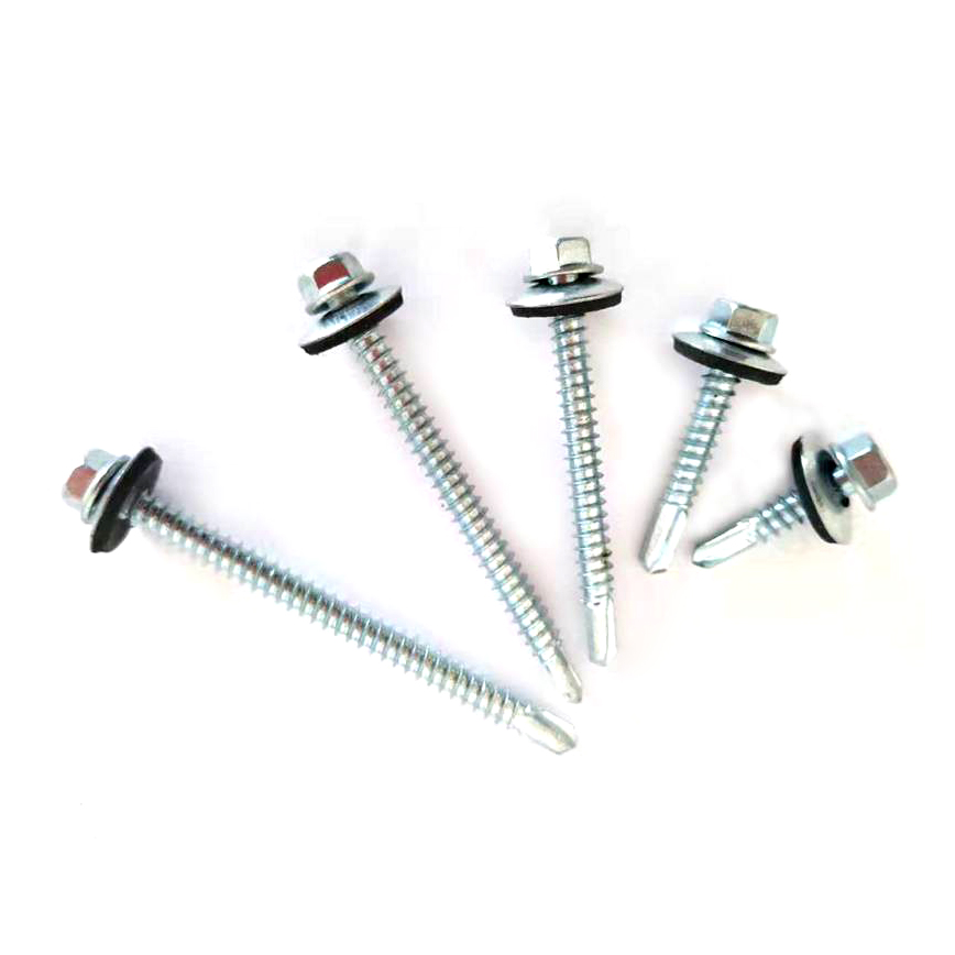
Real-world installation failures stem from predictable operator errors and specification misses. Knowing how to identify and prevent these issues saves thousands in rework and prevents catastrophic joint failures.
Drill point burnout occurs when the point melts, dulls, or blunts before piercing the metal. The primary causes are excessive RPMs or insufficient applied pressure. When a drill point spins too fast without cutting, the friction generates massive heat. This heat work-hardens the base metal, turning the steel surface into a hardened shield that the screw can no longer penetrate.
Mitigation requires adhering strictly to manufacturer-specified RPM limits. Most structural fasteners require 1500 to 2500 RPM depending on the diameter. Operators must apply firm, consistent pressure to keep the point cutting aggressively rather than spinning uselessly against the steel. Never use an impact driver for heavy drilling; the hammering action shatters the hardened drill point.
Thread stripping in thin metal completely ruins the holding power of the connection. This happens when installers use a fine-thread screw in thin sheet metal or apply excessive torque with an impact driver. The high torque rips the threads right through the thin substrate, leaving a loose, spinning fastener.
Mitigation involves utilizing torque-controlled screw guns rather than standard impact wrenches. Specify coarse-thread, undercut fasteners designed specifically for thin panel stitching. The coarse threads grab more material, and the torque-controlled clutch prevents the driver from overpowering the connection once the head seats against the metal.
Point jacking, or layer separation, compromises the joint by pushing the connected materials apart. This occurs when the drill point engages the second layer of metal before clearing the first. The threads bite into the top layer and force it upward while the point struggles to drill the bottom layer.
Mitigation requires ensuring the unthreaded portion of the drill point is longer than the thickness of the top material. This specific geometry allows the top layer to ride freely on the unthreaded section while the point finishes drilling the bottom layer. Once the hole completes, the threads engage both layers simultaneously, pulling them tightly together.
Selecting the correct self drilling screw requires more than matching diameter and length. Tek point capacity, Total Material Thickness, thread pitch, material strength, corrosion resistance, and installation conditions should all be evaluated together to achieve a reliable metal connection.
Established in 2003, Ningbo Weifeng Fastener Co., Ltd. specializes in the development, manufacturing, trading, and service of fasteners and hardware tools, with a portfolio covering screws, bolts, nuts, anchors, and customized fastening products. With more than 20 years of industry experience and products manufactured to standards including GB, DIN, JIS, and ANSI, the company provides an experienced manufacturing background for customers sourcing standard or application-specific fastening solutions.
Calculate your exact Total Material Thickness (TMT) for every unique joint on the project before ordering fasteners.
Cross-reference the calculated TMT against the manufacturer's maximum drilling capacity to select the correct Tek point.
Specify the fastener diameter based on the required shear and tensile loads provided by the project's structural engineer.
Select the appropriate material composition and coating based on the site's environmental corrosivity category.
Request physical fastener samples and conduct on-site mock-up testing to verify drill speed and thread engagement.
A: Self-drilling screws feature a built-in drill bit tip that creates its own pilot hole and taps threads simultaneously in a single motion. Self-tapping screws only cut threads and strictly require a pre-drilled pilot hole before installation. Using a self-tapping screw without a pilot hole will damage the fastener and the metal substrate.
A: Standard formats like 12-14 x 1-1/4" or 10-16 x 19mm break down into three parts. The first number represents the gauge or shank diameter. The second number indicates the threads per inch (TPI). The final number denotes the overall length of the fastener from under the head to the drill point.
A: The difference lies in the shank diameter. A #12 screw has a thicker diameter (approximately 0.216 inches) compared to a #10 screw (approximately 0.190 inches). The larger diameter of the #12 fastener provides higher shear strength and tensile capacity, making it suitable for heavier structural applications.
A: Penetration capacity depends entirely on the Tek point size. A Tek 2 point handles up to approximately 0.110 inches or 26-gauge steel. Conversely, a heavy-duty Tek 5 point features elongated flutes and can penetrate structural steel up to 1/2 inch thick without burning out.
A: The Tek numbering system measures the drill point length and flute design, which corresponds to the maximum drilling thickness. A higher Tek number indicates a longer drill point and deeper flutes, allowing the fastener to evacuate metal chips and penetrate thicker steel substrates without failing.
A: True self-drilling screws do not require pilot holes. Their engineered drill points are designed to cut through metal independently. However, they must be correctly matched to the metal thickness. If the material exceeds the drill point's capacity, the fastener will fail.
A: Burnout occurs due to incorrect installation techniques or improper specification. Using excessive RPMs, applying inadequate pressure, or attempting to drill through a Total Material Thickness (TMT) that exceeds the fastener's specific point capacity causes the drill tip to overheat, dull, and fail instantly.